The No. 1 UK Magazine for electronics technology and computer projects


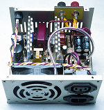
![]() A "dirt cheap" High Current Power Supply. An extensive article describing how to modify a spare standard PC power supply, in order to provide 13.5V at up to 17 Amps. Many old computers have power supplies that can be adapted or re-used, and our fully-illustrated article shows you step by step how to modify a typical PSU to provide a high current source at a regulated +13.5V.
A "dirt cheap" High Current Power Supply. An extensive article describing how to modify a spare standard PC power supply, in order to provide 13.5V at up to 17 Amps. Many old computers have power supplies that can be adapted or re-used, and our fully-illustrated article shows you step by step how to modify a typical PSU to provide a high current source at a regulated +13.5V.
![]() WARNING! HIGH VOLTAGES ARE PRESENT IN A SWITCHED-MODE POWER SUPPLY. THIS PROJECT IS TO BE ATTEMPTED BY FULLY EXPERIENCED AND VERY SKILLED CONSTRUCTORS ONLY.
WARNING! HIGH VOLTAGES ARE PRESENT IN A SWITCHED-MODE POWER SUPPLY. THIS PROJECT IS TO BE ATTEMPTED BY FULLY EXPERIENCED AND VERY SKILLED CONSTRUCTORS ONLY.

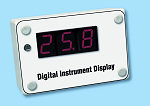
![]() Digital Instrument Display for Cars (Part 2) — Now you can convert analogue instruments to a digital display using our PIC-based project. Suitable for connection to variable resistance or voltage output sensors, to monitor fuel levels, oil pressure or engine temperature. Adjustable alarm level, and automatic display dimming in low light levels. Free source code available from our Downloads page. Calibration procedures and connection details are offered this month.
Digital Instrument Display for Cars (Part 2) — Now you can convert analogue instruments to a digital display using our PIC-based project. Suitable for connection to variable resistance or voltage output sensors, to monitor fuel levels, oil pressure or engine temperature. Adjustable alarm level, and automatic display dimming in low light levels. Free source code available from our Downloads page. Calibration procedures and connection details are offered this month.
![]()

![]() PIC SUDOKU - a brilliant PICmicro-powered handheld game that will entertain you for ages. Also included is exclusive puzzle-solving software that runs on a Windows PC.
PIC SUDOKU - a brilliant PICmicro-powered handheld game that will entertain you for ages. Also included is exclusive puzzle-solving software that runs on a Windows PC.
This exclusive EPE design creates a standard 3x3 number grid on a graphics LCD, ready for you to fill in the missing digits using the keypad. Our free software is available in our Downloads page as usual.
![]()
ALSO IN THIS ISSUE
- Techno Talk on "Terahertz" - the anti-terrorism solution?
- PIC n MIX - Multiplexing - A Trick or Two.
- Practically Speaking - basic project building and soldering techniques
- Circuit Surgery on Schmitt Trigger circuits.
- Net Work - The Internet page- How to use the EPE web site; Vonage VoIP.
- Teach-In 2006 (9) Bistable investigation; Microprocessors & Microcontrollers.
All this and more in the No 1 UK electronics technology magazine
 PLEASE TAKE NOTE: Ingenuity Unlimited July 2006. Page 40, Fig. 1. The lower end (contact) of potentiometer VR1 should be shown connected directly to the 0V line and not the junction of S3/ TR1 base as shown.